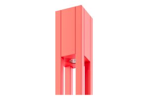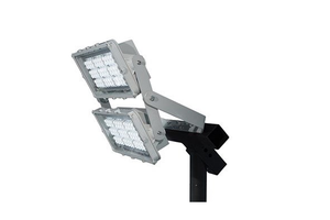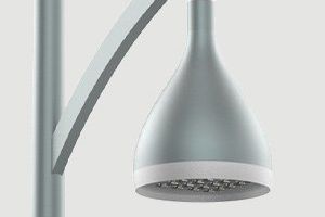


Aluminum lighting pole during exploitation is affected not only by the loads presented by the luminaire or other equipment, bracket and its own weight, but also by wind and snow pressure. As a result of these loads, the lighting pole undergoes by the following:
- the resultant force of wind pressure, which is applied to a certain height, closer to the top of the column (F);
- bending moment, which is largest in the plane of the main column plate (BM);
- the twisting moment (torque) that arises for a pole equipped with a bracket (T);
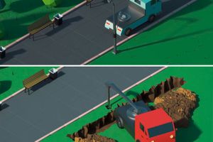
These loads should be supported by a concrete base mounted in the ground.
The stability of the concrete foundation in the ground is a complex question because it is affected by many factors, such as the type, granulometric composition and degree of soil compaction, the location of the concrete footings with respect to the slopes and faults of the soil, freezing depth and others.
Table 1 shows a simplified soil division into categories by their characteristics.
Table 1. Ground category and its condition, as well as selected geotechnical parameters
| MAIN GROUND CATEGORIES AND CONDITION | SELECTED ORIENTATIVE GEOTECHNICAL PARAMETERS OF THE GROUND | ||||||
| φ [°] | c [kNm2] |
γ [kNm3] |
C [kNm3] |
f | qg [MPa] |
||
| CATEGORY I Stiff ground |
Heaps, rubble, gravels, gravel shores, coarse and medium-concentrated sands, and medium-compacted, fine sands | 35 | 0 | 18,5 | 15000 | 0,55 | 0,30 |
| Dusts, compacted clays, clays, loam gravels, gravel shores, semi-solid sands and hard plastic sands | 20 | 25 | 20 | 20000 | 0,25 | ||
|
CATEGORY II |
Heaps, rubble, gravels, gravel shores, coarse loose sands, fine and silty sands, medium concentrated | 32 | 0 | 17,5 | 12000 | 0,45 | 0,25 |
| Dusts, clays, compacted clays, clays, loam gravels, gravel shores and plastic clay sands | 15 | 15 | 19 | 10000 | 0,30 | ||
|
CATEGORY III |
Fine and dusty sands, loose, humus sands moderately concentrated | 25 | 0 | 15 | 10000 | 0,35 | 0,20 |
| Dusts, clays, compacted clays, loam gravels, gravel shores, soft plastic clay sands | 10 | 5 | 18 | 5000 | 0,1 | ||
where:
φ - angle of internal friction,
c - consistency,
γ - unit weight,
C - ground vulnerability module,
f - coefficient of friction of the ground against the concrete footing,
qg - ground boundary resistance.
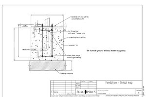
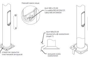
To ensure adequate stability of the pole, a suitable typical prefabricated concrete footing must be used (foundation unit) or anchoring concrete made at the place of installation of the pole.
The selection of concrete footings and making of cast-in-place concrete with the use of anchoring devices Z-type can be carried out on the basis of the d'Andree and Norsa formula:
 ,
,
where:
Ms - moment of concrete footing stability,
Nc - total load on the ground (sum of weight: pole, equipment and concrete footing),
A - concrete footing side width,
H - concrete footing height,
qg - ground boundary resistance.
The stability of the structure will be maintained if the following condition is met:
![]() ,
,
where:
Mg - moment on the column at the base-plate,
T - shear force on the column at the base-plate,
H – concrete footing height.
Table 2 provides stability moments for individual types of prefabricated concrete footings for III category of ground with typical standard pole load.
Table 2. Types of concrete footings and their moments of stability for III category of ground (qg = 0.2 MPa)
|
Concrete footing type |
Concrete footing side [mm] | Height H [mm] |
Spacing and type of bolts | Weight [kg] |
The stability moment of concrete footing with a typical load Ms [Nm] |
| B-50 | 240 | 900 | 180 - M14 | 95 | 8000 |
| B-51 | 260 | 1000 | 200 - M18 | 122 | 10000 |
| B-51A | 260 | 1200 | 200 - M18 | 148 | 14000 |
| B-60 | 320 | 1000 | 250 - M18 | 168 | 12000 |
| B-71 | 400 | 1000 | 300 - M24 | 250 | 14000 |
| B-70 | 400 | 1200 | 300 - M24 | 296 | 20000 |
| B-80 | 400 | 1500 | 300 - M24 | 380 |
3200 |
For the assumptions made above, the concrete footing type is assigned to the type of column as follows (table 3):
Table 3. General classification of concrete footings for the types of poles assuming a minimum of III category of grounds as in Table 2
| Concrete footing type |
Height H |
Column types - base-plate diameter x base-plate side x bolt spacing | Maximum possible heights of the columns used |
| B-50 | 900 | 114 120 with a 224x180 base-plate including SAL SYG | 6 |
| B-51 | 1000 | 114 D60 120E 146g with a 260x200 base-plate | 7 |
| B-51A | 1200 | 114 D60 120E 146g with a 260x200 base-plate* | 7 |
| B-60 | 1000 | 146 with a 320x250 base-plate | 8 |
| B-71 | 1000 | 146H 176 178K 180M with a 400xz300 base-plate with single and double extension arms up to 1.5m outreach length | 12 |
| B-70 | 1200 | 176 180M with a 400xz300, base-plate including versions wzm | 12 |
| B-80 | 1500 | MAL-type columns with a 400xz300 base-plate | 16 |
* Higher concrete footings with a higher stability moment should be used in the following cases:
- when mounting on columns equipped with extensions with three or more arms (brackets);
- when installed on slopes or near the slopes at their top;
- in the case of mounting column in soil with very low load-bearing characteristic.
In any other case, when the prefabricated concrete footing is insufficient, a cast-in-place concrete should be made at the place of installation of the column with appropriate dimensions using a Z-type reinforcement basket (anchoring device).
The above selection of concrete footing type and anchoring device for lighting poles is only approximate. The proper use of a suitable concrete footing requires a detailed analysis of ground conditions. The foundation of the concrete footing for the lighting column in each case takes place in a specific, often heterogeneous ground, which can only be recognized in detail by authorized persons. Therefore, the selection of concrete footings contained in this description should be treated only as a guide.
Information taken from the official Rosa website