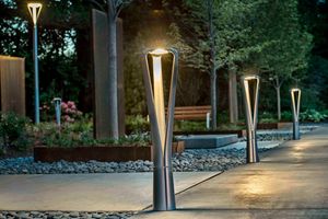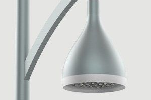


For qualitative lighting of roads, streets and large areas, an integrated approach is required, which lays in the proper technical and economic selection of equipment based on lighting engineering calculation, the choice of design of poles and lamps so that they look harmoniously against the background of urban architecture, as well as in the correct installation of lighting poles on the quality of which depends the further operation of the lighting system.
There are several options of installing galvanized lighting poles of Europoles brand that are different from one another with their concrete footings (foundations) manufacturing methods and the construction of the support (those with flange plate or those mounted in the ground):
- assembling of the EUROPOLES lighting supports of CC and 0SH types on to the anchor device; in this case the reinforcement of the footing (anchor device) is filled with concrete directly at the place of installation;
- assembling of the EUROPOLES lighting support off CC and 0SH types onto the concrete footing that is delivered in one finished construction to the necessary place;
- mounting/digging in the EUROPOLES lighting supports directly into the soil.
1. Project documentation
Before the installation of lighting technical equipment the project has to be developed that will take into consideration the following nuances:
- On the basis of general plan of the object and technical task from the customer the information about the relief and landscape, laying ways of existing communication wires on the terrain, size and type of the terrain and structures to be lightened must be provided.
- in accordance with State Building Regulations B.2.5-28: 2018 Natural and artificial lighting is determined by the required level of illumination and a number of parameters, which depends on the type of object to be lightened;
- the optimal number of poles, their height, power and number of LED fixtures are selected on the basis of the lighting engineering calculation and the place of installation that will meet the requirements of regulatory documents is determined;
- on the basis of the wind zone, the category of the territory, the aerodynamic resistance of the selected luminaire and their number on the support, the parameters of the bracket (the number of angles and the length of mounting plate), the necessary thickness of the pole's wall and the diameter of its ending are selected;
- by knowing the power of the luminaire and its location, the length of the route is calculated and the required intersection of the wires of the cable line is chosen taking into account the current load and voltage downfall, which shouldn't be more than 5% according to Electrical Installation Rules (ukr.abbreviation - ПУЕ) 2017;
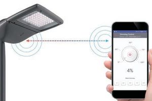
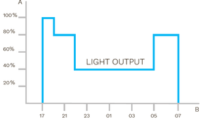
- a lighting control scheme (outdoor lighting shield) is being elaborated, as well as the possibility of future integration into the Smart City concept, which will allow to regulate the lighting system (switch on and off, make the dimming light), to apply various sensors in smart lighting systems (motion sensors, speed radars, etc.) and to monitor the condition and power consumption of the lamp.
2. Installation of a cable line to be connected to the lighting pole
-
The initial stage of construction works is the clearing and planning of the particular site. With the help of leveling, according to the project, checkpoints at which the lighting poles are going to be situated are marked down.
-
Between the points of mounting the poles with the help of special machinery or manually, a trench is dug for laying the cable line (CL) which depth should be at least 0.7 m from the soil surface (taking into account the sand stratum- 0.8 m). If the cable is reinforced it is laid without using pipes. In the case when cable is not reinforced, it must be protected from outside factors by specialized electrotechnical pipes used exactly for these purposes.The most favorable option is to use double-wall corrugated pipes of the appropriate intersection and length, the rigidity of which is selected considering the ground properties and the degree of likelyhood of occurrence of unwanted mechanical damages, which are assumed to happen at the design stage. After pouring and ramming a layer of sand with a height of at least 0.1m or small-grained, clean soil without inclusions, the cable or cable in the double-walled pipe are layed and then it must be checked for any short circuit between the wires and the wires and protective covering. At a distance of 0.25 m from the cable a signal strip is laid (pouring up to this mark, as well as further backfilling to the soil surface is accomplished by previously excavated unprepared soil). Afterwards the final filling of the trench comes about, taking into account the further shrinkage of the ground after the rain and the conclusive check for the absence of short circuit between the wires (veins) and between the veins and the shield. The eventual depth of the CL and safe distances from structures or other communication objects, both terrestrial and subterranean, should be determined on the basis of the applicable normative regulations at the project stage in relation to the specific object.
-
At the points of mounting of the poles a pit (hole) is dug in where an anchor device (reinforcement basket) or concrete footing is inserted. Depending on the chosen method of mounting of the footing, the dimensions of the pit and the order of installation of the footing are written in paragraphs 3.1 and 3.2.
-
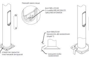
At the places of cable (reinforced and non-reinforced) input into the concrete footing (ready-made concrete footing or anchoring device with subsequent pouring of concrete), the cable must be protected by electrotechnical pipes along the whole height of the concrete foundation. In the anchoring device, when laying the cable in the electrical pipe, the last one must pass through the center of the pit and the anchor device, necessarily going through the opening hole of the upper plate which diameter varies depending on the type of anchor, which must be taken into account when choosing the diameter of the pipes. For the digging poles, the cable connection to the pole is performed in the electrical pipe. The length of the pipe running inside the support must be at least to the surface of the ground. When entering the pipe into the lighting pole, you have to note the dimensions of the oppening in the underground part of the support, which are 50x150 mm. The length of the power cable in the above-ground part must be sufficient to be freely connected to an fuse box that is mounted in the niche of the support. The dimensions of this recess vary depending on the height of the support, which should be taken into account when selecting the fuse box (input shield).
-
Further installation of galvanized lighting poles is carried out in accordance with paragraph 4.
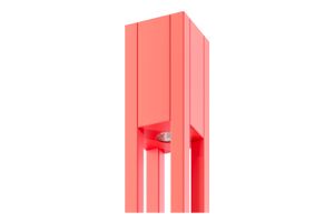
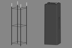
3.1. Installation of EUROPOLES reinforcement basket type "FP" (Fig. 1)
- Put the reinforcement basket (foundation reinforcement) of type "FP" (FP1, FP2, FP3, FP4, FP4-1) in a prepared pit, which should be more than 10 cm larger than the size of the reinforcement basket.
- To carry into the reinforcement basket electrical pipes with cables inside of them (at this phase, according to paragraph 2 there must be the performing of the cable laying). There has to be enough length of pipes exiting the surface through the hole in the upper mounting plate to allow a certain reserve to remain after pouring the concrete.
- Next, formwork and filling the anchorage with concrete of class not less that C25/30 shall be completed.ATTENTION! Concrete pouring should be done below the design mark by a value sufficient to install the pole on the nuts and to level its flange with the design mark using steel paddings and subsequent concrete pouring (see paragraph 4).
- After pouring the concrete, it takes some time for the concrete to gain design strength. This needed time depends on environmental conditions (air temperature, humidity, volume of concrete, etc.) and it usually takes a few weeks (at ambient conditions of 15–25° C (288–298 K) and a relative humidity of 90–100% it's necessary to give it 28 days for solidification).
- Further installation of galvanized lighting poles has to be accomplished in accordance with paragraph 4.
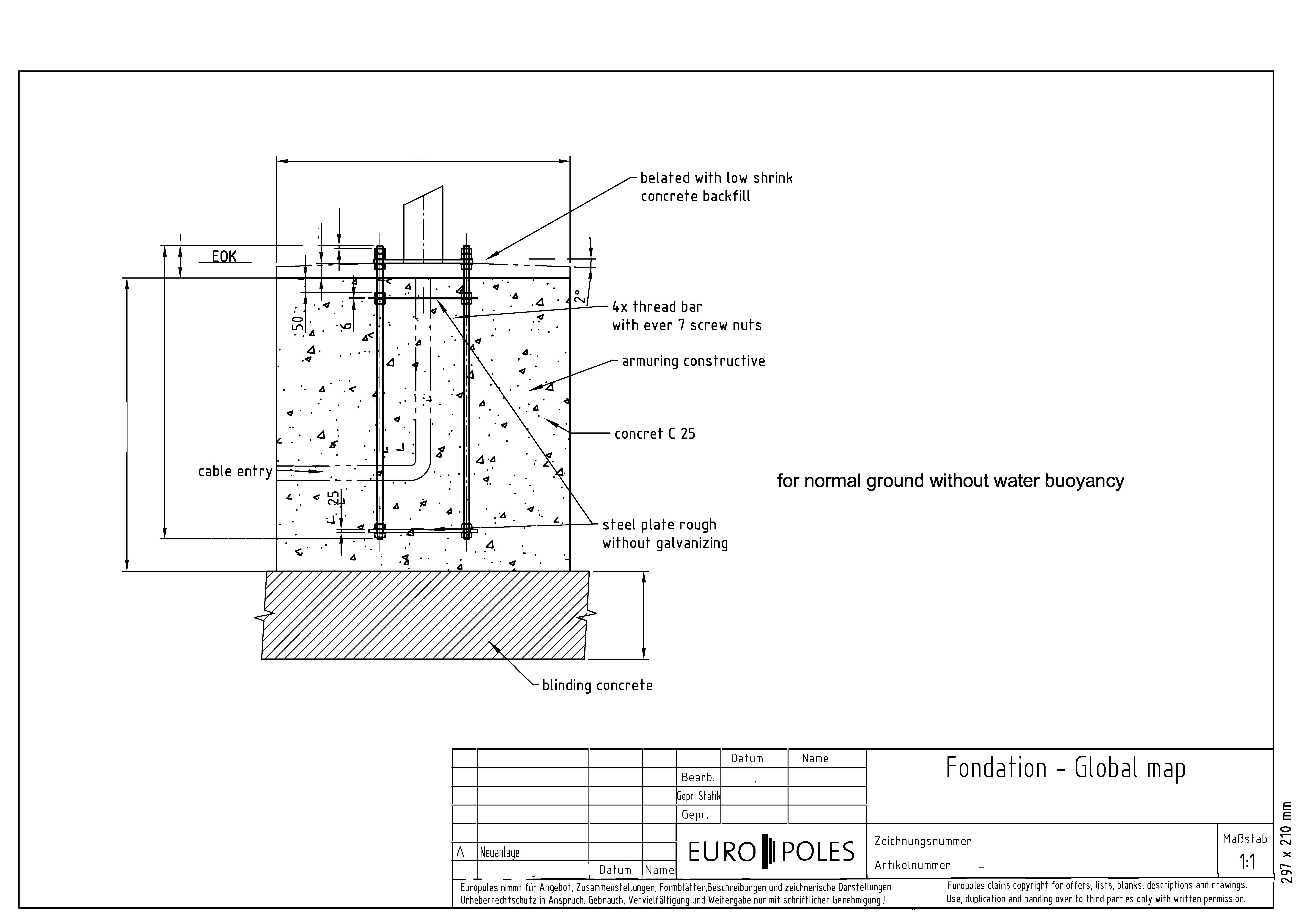
Fig.1 - Installation of EUROPOLES reinforcement basket type FP1, FP2, FP3, FP4, FP4-1
3.2. Installation of EUROPOLES concrete foundation type F100/30 (F150/430)
In this case, prefabricated precast concrete blocks are delivered to the site where the construction works take place with no need for concreting, which accelarates the installation process, sinceyou don't have to wait for the concrete to solidify. The process of installation of the concrete foundation takes place in several phases:
- A hole is being dug - 0.15 m wide larger than the transverse dimensions of the finished concrete foundation, manually or by special equipment at the control point at the site of the installation of the lighting pole. The depth of the pit should be equal to the height of the concrete foundation and correspond to the design height of the column installation. At this stage, accordingly to the paragraph 2 the laying of the CL is being performed.
- After prior securement of the concrete foundation with anti-corrosion protection, with the help of special equipment, the concrete foundation is placed in the pit, running through the special openings of the cables in the protective pipes and leveled according to the design marks. ATTENTION! Only the accurate alignment of the top of the concrete foundation horizontally guarantees the correct installation of the pole vertically.
- The concrete foundation is backfilled with previously dug soil. Backfill should be accomplished with layers up to 0.2 m of thickness with following ramming. The procedure must be repeated until the soil surface is reached.
- Further installation and connection of poles has to be carried out accordingly to paragraph 4.
3.3. Installation of EUROPOLES KLM type lighting poles directly into the ground
- Pits with dimensions sufficient for further installation are being excavated at the points at which the supports will be located. It is recommended to prepare a pit with a minimum width of 3 times the lower diameter of the pole and a depth that depends on the height of the pole.
- Installation of lighting equipment has to be carried out accordingly to paragraph 4.
- With the help of special equipment in accordance with the recommendations given in paragraph 4, place the pole in the pit and conduct the laying of the cable in the electrical pipe into the pole.
- Fill with concrete of category not lower than C25/30.
- Execute the installation of the fuse box in the recesses of the pole and the connection of the cable line and the power cable of the lamp. Install the fuse into the fuse box.
4. Installation of galvanized lighting poles EUROPOLES
Before setting the pole on the concrete foundation (the concrete foundation refers to a pre-assembled concrete block or reinforcement basket, the concrete in which has gained design strength and solidity), it is necessary to mount the bracket, if it is provided by the project, and also perform the mounting of the luminaire on the fixture of the pole or bracket and lay the cable inside the pole from the lamp to the pole's niche.
- Preparatory works. Before starting the mounting of the bracket, it is necessary to: check the fullness of the set of M10 screws located at the top of the pole (8 pcs); examine the opennings and screws mentioned above for dirt and mechanical damage and after that lubricate with a viscous grease.
- Mounting the bracket. The bracket should be mounted in a horizontal position, for this purpose, at a distance of 7/8 from the length of the pole, a wooden backing (stand) should be placed in order to make the bracket not to touch with its horns to the ground (Fig. 2). The pole's flange must also be on a wooden backing.

Fig. 2 - Mounting of the bracket
During the setting down of the bracket by tightening the screw on one side, it needed to be kept in mind that the screws located on the opposite side have to be unscrewed beforehand, thus preventing possible damages to the thread and placing the bracket in the center of the column. It is suggested to carry out electrical installation simultaneously with the mounting work of the brackets (putting power cables in the bracket and pole, attachment of the lighting fixtures). After installing the bracket in the required position, proceed to the final stage, namely fixation of the bracket, which prevents dislocation (Fig. 3).
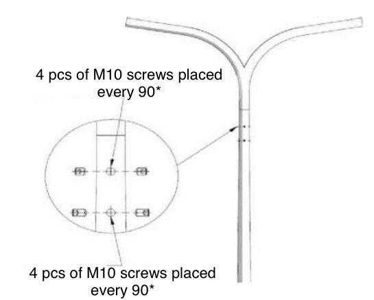
Fig. 3 - Fixation of the bracket
Tightening of the positioning screws is implemented with the help of torque wrench. The required tightening moment is in the range from 25 Nm to 35 Nm. Loose tightening can cause insufficient fixation and, if the ultimate force is exceeded, then it leads to rupture of the thread and loss of stability of the connection.
3. Before proceeding with the vertical transportation of the assembled structure of the pole, it is recommended to provide a further scope of work by preparing next instruments: screws and washers of anchors, wrenches and wooden blocks. In order to install the pole in an upright position with the desired accuracy and for aesthetic reasons theodolite or level is needed. For this purpose, the preparation of steel lining with dimensions 50x80mm and thickness from 2.4 to 6 mm, made of flat strips or metal sheets, one edge of which should be polished, will also be suitable. The total area of steel linings packages must be at least 15% of the surface of the plate sheet of the pole (flange), given that for each of the foundation screw two packages are required.
4. Thereafter, using a transport belt or elastic hemp rope lift the pole with the help special equipment. The point of force application (the arrangement of position of the rope or belt) should be just above the center of gravity of the pole (Fig. 4).
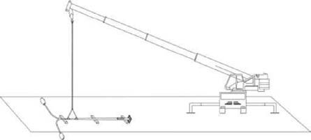
Fig. 4 - Lifting the pole with the help of special equipment
It should be remembered to protect the cable from sliding. Installing of the pole in a position close to the vertical has to be carried out without dynamic loads (without sharp moves). When the pole base (flange) is raised above the ground, carefully move the pole to the foundation, set the pole down to a pre-prepared base with dimensions that do not allow the base to lean on the anchor cores (use wooden substrates (linings). Then drag out the power cables from below, remove the wooden substrates and direct the anchor openings on the pole's flanges with the threaded studs located in the foundation. It is necessary to previously screw in the first set of nuts (4 pcs) on which the poles must be placed (see Fig. 1).
5. After mounting the construction on the foundation block, the substrates should be instantly installed and the nuts should be tightened. Modification for a more precise mounting of the pole in the upright position can be done by unscrewing the fixing nut and lining the steel wedges. The top surface of the packs should correspond to the lower surface level of the pole's base sheet. Placing of permanent packages should allow the cement mixture to be filled in a circle at width of at least 25 mm. The checking on deviations is executed by use of the above-mentioned measuring instruments. After installing the support in the proper position, the nuts (both the lower and the upper two - see Fig. 1) should be screwed up if needed and the verticalness of the structure re-checked. The deviation of the longitudinal axis of the pole rod from the vertical position must not overrun f <2.5 mm/m.
6. Zone for future cement filling located under the pole flange should be cleaned straight before cementing. It is recommended to do the backfilling with Portland cement of not lower than mark of 35, depending on the thickness of the cement layer t<25 mm - cement mix, 25 <t <50 mm - cement mortar 1:1; t>50 mm - cement mortar in the proportion not less than 1:2 or fine-grained concrete of mark not less than C25/C30. It is possible to cement only at a positive temperature, unless otherwise stated in the manufacturer's instructions. The cement mortar before application should be mixed and used with appropriate consistency: in liquid form for cementing and for pouring, so that the free space under the flange is totally filled. After the installation of the pole, a possible adjustment of the position of the supporting structures in order to comply with safety conditions should be performed using hoisting machines.
7. After the final installation, it is necessary to grease all screw connections on the foundation (the upper two nuts) with technical vaseline and apply on top a plastic plug, which provides a protection for the connection from corrosion and moisture and aggressive substances hit.
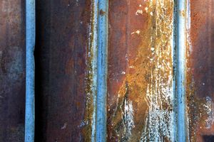
8. When installation, special attention should be drawn to the careful handling of a layer of anti-corrosion coating, the thickness of which is approximately 70 Nm. Remember that the foundation could be easily deformed as a result of overload, both static (applying a large number of layers of packets) and dynamic (hitting during unloading or transportation). It is suggested to take care of small structural components that may be lost during transportation.
9. Execution of the installation of the fuse box in the niche of the pole and connection the cable line and the power cable of the lamp. Placing a fuse in the fuse box.
ATTENTION! The above written information on the installation of reinforcement baskets and concrete foundations is only advisory in nature, since the eventual instructions for the installation of reinforcement baskets and concrete foundations are provided only by the Chief project engineer according to the soil properties and the location where the lighting equipment will be installed.