


Assembling of aluminum ROSA lighting poles requires thorough preparation and following to clear guidelines for the installation of poles, the quality of which depends on the further operation and reliability of the outdoor lighting system.
Main stages for installing ROSA aluminum poles
- Project development and planning. At this stage, for the optimal feasibility study of the choice of lighting equipment ROSA on the basis of lighting engineering calculation and current regulatory documents [State Building Standards of Ukraine V.2.5-28: 2018 Natural lighting and lamplight] the required number of lighting poles, fixtures and their power, type of optics, as well as their placing are being selected. Based on the gotten results (the height of the aluminum poles, the type of LED lamps, their number on the pole, etc.) and the category of terrain and wind load, the lighting poles of the necessary durability and fixity are being chosen. Knowing the placement of the lighting poles and the power consumption of LED lamps, a cable line (CL) laying scheme is being developed, the required cable length and the choice of cross-section are determined taking into account the voltage fall, which should be no more than 5% [Rules of arrangement of electrical installations 2017].
- The initial stage of construction work is clearance and planning the territory. With the help of level, according to the project, control points at which the lighting poles will be located are marked.
- Digging trenches for laying cables, foundation pits for installing concrete foundations of B-type or anchor devices (reinforcement basket) of Z-type.
- Concrete foundations or reinforcement basket installation and their fixation in the soil.
- Mounting of lighting poles on the foundation, their connection to the power network and commissioning of the outdoor lighting system.
Installation of a cable line (CL) for connecting of the aluminum lighting poles
- The initial stage of construction work is clearance and planning the territory. With the help of level, according to the project, control points at which the lighting poles will be located are marked.
- Between the mounting points of the lighting poles by dint of special facilities or manually, a trench is dug for laying a cable line (CL) which depth should be at least 0.7 m from the ground surface (taking into account the sand cushion - 0.8 m). If the cable is armored then it is laid without using of pipes. In the case of using a non-armored cable, you have to to protect it from external factors by specialized electrotechnical pipes that are used specifically for these purposes. The most optimal option is the use of double-walled corrugated pipes of the appropriate section and length, the hardness of which is selected considering the properties of the soil and the degree of likelihood of occurrence of objectionable mechanical damages, is expected to be at the design stage. After adding and compressing a layer of sand with a height of at least 0.1 m or small clean soil without inclusions, a cable or cable in a double-walled pipe is being layed and checked for absence of the short circuit between the between the wires and wires and armor. Next, the CL is filled up and compacted with fractional soil or sand with a layer of a thickness of at least 0.1 m. At a distance of 0.25 m from the cable, a signal strip is established (bedding this mark, as well as further backfilling to the surface of the soil is performing by previously dug excavated soil). Then comes a final filling of the trench, taking into account further shrinkage (compressing) of the ground after rain and a final examination for the absence of short circuit between the conductors and between the conductors and the screen. The eventual depth of the CL and the safe distances from the building and other structures, both above-ground and underground, should be determined on the basis of the current regulatory documents at the project stage particularly with respect to the specific object.
- In places of cable inlet (both armored and non-armored) into the concrete foundation (ready-made concrete footing or anchor device (reinforcement basket with subsequent pouring of concrete) it has to be protected by electrotechnical pipes along the entire height of the concrete foundation. In the anchor unit, when laying the cable in the electrical pipe, it must go through the center of the pit and the reinforcement basket, obligatory passing through the hole of the top plate, the diameter of which varies depending on the type of anchor, which should be taken into account when choosing the diameter of the pipes. The length of the power cable in the In terrestrial part must be sufficient to be freely connected to the fuse box that is mounted in the niche of the column.
- Subsequent installation of galvanized lighting poles is carried out in accordance with the recommendations listed below.
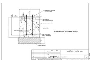
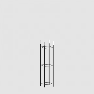
Installation of ROSA anchor device (reinforcement basket) of Z-type (Fig. 1)
-
Reinforcement basket type “Z” is to be placed in prepared pit, which should be 10 cm bigger than dimensions of basket.
-
Place plastic pipe which enables to insert later a feeding cable. Pipe diameter should be appropriate for type and quantity of cables.
-
Make cement mortar (class min. B-20) up to the height of bottom edge of insulating sleeves, which are placed on screwed ferrules.
-
Surface of concrete must be exactly leveled in order to ensure the adhesion of column’s base. ATTENTION! Only exact leveling of mortar assures vertical position of column!
-
Apart from columns with elastomer protection, as soon as the prepared cement mortar dries out, it has to be covered by bituminous layer of minimum thickness 250 μm or by other material of required thickness and the same protection degree.
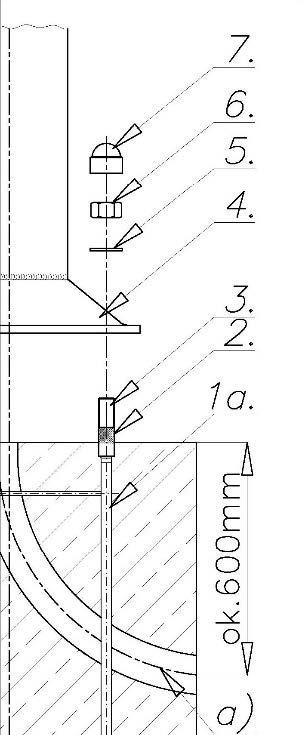
Fig. 1 - Installation of aluminum column on reinforcement basket ROSA Z-type, where:
1a. Reinforcement basket Z-type; 2. Insolating sleeve; 3. Hot galvanized screwed ferrule; 4. Column base; 5. Stainless washer; 6. Hot galvanized nut; 7. Protective cap; a) Plastic pipe for inserting feeding cables
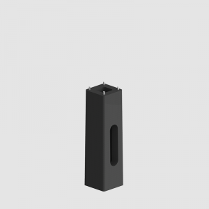
Installation of ready-made ROSA concrete footing of B-type (Fig. 2)
In this case, precast concrete blocks, that are installed in the ground without the need for concreting, are delivered to the building site as it accelerates installation and it is not necessary to wait for concrete to gain design strength. The process of installing concrete anchors takes place in several stages:
- Concrete base type “B” is to be placed in prepared pit.
-
Insert the feeding cable in the protective cover into the corresponding hole in the concrete footing. Dig in concrete base in the ground, insert feeding cables, level and beat down ground around the base. ATTENTION! Only exact leveling of upper surface of concrete base assures vertical position of column! Concrete footing should be buried deep enough that after tamping and ground leveling around was at the same ground level or protrude max 20mm.
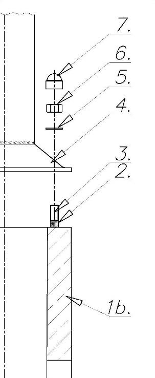
Fig. 2 - Installation of aluminum column on the ready-made ROSA concrete footing B-type, where:
1b. Concrete footing type “B”; 2. Insolating sleeve 3. Hot galvanized screwed ferrule 4. Column base; 5. Stainless washer; 6. Hot galvanized nut; 7. Protective cap; (The figure does not show the input of an electrotechnical pipe, which must be brought into the column through a special niche in the concrete footing)
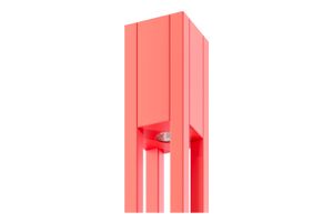
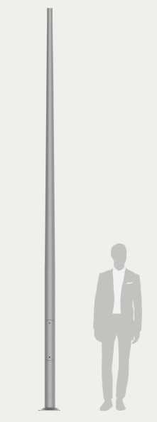
Installation of ROSA aluminum columns (Fig. 1 - Fig. 3)
-
As for columns, which are not protected with polyurethane elastomer, it is recommended to cover them (bottom part up to height of 350mm) inside and outside by bituminous layer of minimum thickness of 250 μm or by other material which ensures the same protection.
-
Twist off niche’s cover.
-
Place aluminium columns on the studs of preliminary on studs (screwed ferrules) of pre-cast anchor device or ready foundation inserting feeding cables into niche.
-
For each screwed ferrules put washer and tighten up nut. It is suggested to use original connection elements.
-
Clean properly nuts, dry them out and cover by technical vaseline (or other anticorrosive mean) and then put on protective caps.
-
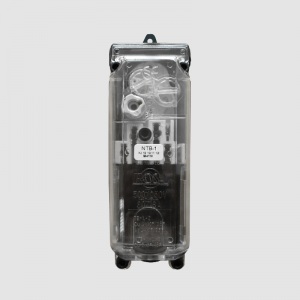
Connect feeding cables in connection box according to instruction of assembling connection box TB-, NTB-type and tighten up niche’s cover torquing the bolts.
-
In order to ensure adequate cathodic protection connect the ground wire to the grounding terminal in OPTION 1 or OPTION 2 (figure 3).
-
After assembling remove the fibre material from product’s surface.
Attention! Installation of the luminaire have to be made immediately after mounting a column or a column with a bracket! Unloaded columns or columns with brackets can fall in high frequency vibration which can result in their damage.
.png)
Fig. 3 - Connecting earthning to the aluminum lighting pole
ATTENTION! The above-indicated information on the assembling of reinforcement baskets (anchor devices) and concrete footings is only advisory in nature, since the final instructions for the installation of reinforcement baskets and concrete footings are provided only by the chief project engineer according to the properties of the soil and the terrain where the installation of lighting equipment will be carried out.
 |
 |
 |
 |
|||||
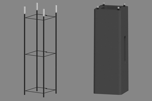
ROSA ANCHOR UNITS (REINFORCEMENT BASKETS) |
ROSA CONCRETE FOOTINGS |
ROSA FUSE BOXES |
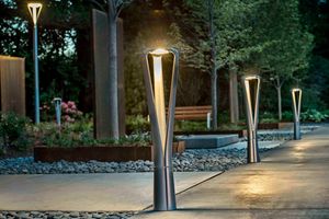
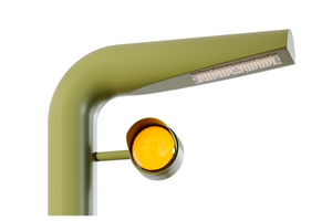
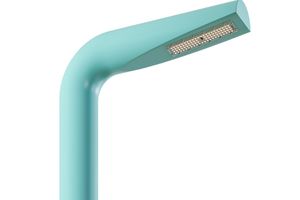
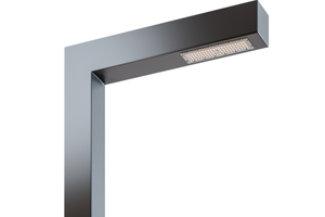
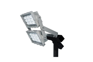
ROSA ALUMINUM LIGHTING POLES |
|